• Home
  • Blog
  • About
  • Contact Us
Menu

Robust Review

Fast Construction Drawing Review and Coordination
  • Home
  • Blog
  • About
  • Contact Us

A Case of the Vapors...

February 21, 2017

The Problem:  Water Vapor Emission is an often overlooked, misdiagnosed, and misunderstood problem, and it can lead to damaged flooring on new and existing floors.

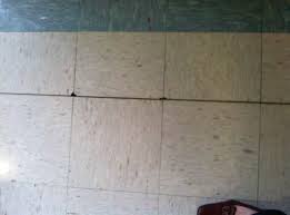
The Cause:  Water can migrate upward and through concrete substrates in the form of water vapor, and then condense and accumulate in the space between a concrete slab and the flooring.  Concrete slabs-on-grade are especially vulnerable to this phenomenon, but elevated slabs can experience this problem too.  Most flooring is adhered to the concrete substrate with a glue or adhesive, and all adhesives have a limit as to how well they can "stick" the flooring to the concrete under these conditions.  The accumulated water interferes with most adhesives and soon the flooring is loose and can shift, float, bunch up or cause gaps in flooring.  Additionally, the water can damage the flooring material itself, especially if it is made from natural or water-absorbent materials.  The end result is a damaged floor and a significant risk of tripping or slip hazards for those who use the building.

The Solution(s):  Most of the solutions to this Water Vapor Emission problem focus on barriers to prevent or limit the amount of water vapor that can migrate to the space between the flooring and the concrete where it interferes with the adhesive.  Many projects use a "belt and suspenders" approach by using more than one of these solutions at the same time to tackle this problem.  Some of the solutions include:

  1. Improved under-slab vapor barrier - This is a vapor barrier that goes above and beyond the typical 6 mil visqueen used for years for slab-on-grade construction.  New products are 10 mil or greater in thickness, with heat-welded seams and heat-welded boots clamped at all floor penetrations resulting in an water-tight seal.  Many product specifications of this type require smoke testing and/or certified installers to ensure quality installation.  The end product is often as water-tight as any single-ply roofing system.
  2. Improved concrete add-mixtures - There are a number of specially formulated concrete add-mixtures that can be added at the concrete batch plant that limit water vapor migration through a concrete slab.  
  3. Water Vapor Emission Control Sealers (new concrete) - These products are normally applied to green (new) concrete 1 to 2 days after a concrete pour by certified installers.  These product are typically applied by spray or by roll and squeegee, requiring 1 to 2 days to cure.  These products also often come with multi-year warranties that include the cost of flooring replacement, and are some of the most effective solutions to the Vapor Emission Control problem.
  4. Water Vapor Emission Control Sealers (existing concrete slabs) - These products are very similar (or often identical) to the Vapor Emission Control Sealers for new slabs described above, but there is an important (and expensive) difference.  Most product manufacturers require that any existing concrete slab be bead- or shot-blasted prior to applying the Sealer product.  This extra step ensures that any existing flooring adhesives or other deleterious material is removed and does not hinder the performance of the Vapor Emission Control product, and that the sealer can properly adhere to the concrete surface.  Unfortunately, this extra bead-blasting step requires additional equipment (e.g.: a bead blaster) and labor, which are often equal to the labor and material cost to install the new flooring itself.  Fortunately, the same multi-year warranties normally apply to the sealer for existing concrete slabs if these steps are followed.

The Lesson:  Make sure to evaluate your project to determine if Water Vapor Emission is a potential risk for any flooring work, explore your options and make sure the project documents outline and reflect your strategy to mitigate this risk.

1 Comment

Those Pesky Tamper Switches

February 12, 2017

File this one under "re-work due to poor Fire Alarm coordination."

Background:  Most Building Fire Alarm systems include one or more tamper switches as part of their monitoring requirements.  In short, it is important that all water valves in the fire sprinkler system are open (at least for conventional wet systems) in the event of a fire.  Many of these valves may need to be shut for maintenance, repair or adjustments to the fire sprinkler system, but the Fire Alarm system is often used to monitor these valves and report when/if they are closed.  

Which valves, you may ask?  There can be several, but often the Position Indicator Valve (PIV), the OS&Y Valves on the backflow device and any other isolation valves on the fire sprinkler riser or similar area.  Often, the PIV and backflow preventer devices are outside of the main building (or buildings), and located close to the street or curb and most likely a fire hydrant.

The Problem:  Since these valves need to be monitored by the Fire Alarm system, we effectively have Fire Alarm devices that are well outside of the building (i.e.: tamper switches on exterior PIV and backflow valves).  So, imagine a new building project that is 80% complete.  The structure is up, the roof is on, the building is enclosed, the electrical is roughed in, and the Fire Alarm contractor shows up to the jobsite with his Fire-Marshall-approved drawings.  These drawings require tamper switches on the new PIV and backflow devices near the street.  However, the sitework is also 80% complete including a paved driveway entrance and extensive ADA-compliant sidewalks, and that driveway and sidewalk system sits between the new building and the PIV/backflow area.  

Did someone remember to run a 3/4" conduit between the building and the PIV/backflow area?  Or, do we now have to saw-cut our new paving to create a path to these Fire Alarm devices?  Then, the debate begins about who is to blame for this oversight.  But, the cost is real, the impact to the construction schedule is real, and the scar left on the paving for this re-work will last a lifetime.

This coordination error is (hopefully) an error that a person makes only once in a career, but it can be avoided entirely with a small amount of coordination.  Make sure the electrical sub runs a small conduit along the exterior fire sprinkler supply line before it gets buried, and the re-work described above can be avoided. 


Comment

Utility Alignment

January 30, 2017

One of the first places that I look during a Constructability Review is at the alignment (or mis-alignment) of utilities for the building or buildings.  Because the utility design work is often divided up by the Civil Engineer, Mechanical Engineer, and Electrical Engineer, it is necessary to overlay these drawings to make sure that the types, sizes and locations of each utility are in alignment in all drawings.  Frequently, I have found a 6" sewer line from the building feeding into a 4" sewer line, a natural gas line not aligning with the gas meter location, or the fire sprinkler riser location not shown or not aligned with the water supply line.

My methodology has been to organize and list all utilities needed for a building or buildings and systematically verify each utility type, size and location.  To make your review easier, below is a partial list of utilities that should be considered in a Constructability Review:

  1. Sanitary Sewer / Clean out(s)
  2. Storm Drains / Roof Drains / Rainwater Leaders
  3. Domestic Water / Water Meter
  4. Fire Sprinkler Water / Riser / Backflow / FDC / PIV
  5. Natural Gas / Gas Meter
  6. Electrical Power / Transformer / Meter / Main Switch Board
  7. Data / Communication / MPOE
  8. Fire Alarm / Exterior Devices
2 Comments

Condensate - the overlooked utility

January 25, 2017

Condensate water is often overlooked in both design and construction work, but is important to consider.  Condensate water is normally produced as a byproduct of HVAC equipment.  The most obvious would be at the evaporator, but that evaporator can be part of a packaged unit or separated out in a split HVAC unit.  More importantly, these units can be in a number of locations which dictates the need for condensate lines:

  1. Roof-top Units - Depending on local building codes and requirements, the condensate from roof-top units can be redirected to drain directly to the roof, or to be plumbed to either roof drains or even sanitary sewer lines.  If plumbed condensate drain lines are required, make sure that detailed drawings are provided that spell out any air gap, p-trap and ventilation requirements.
  2. Exterior pad-mounted units - Again, depending on local building codes, HVAC units that are mounted at the exterior of the building can drain their condensate to a landscaped area or a french drain or similar location.  However, what is often overlooked is the path that this water takes.  Whether it is plumbed with a drain line or drains directly from the HVAC unit, make sure that it doesn't cross any sidewalks or would possibly stain an otherwise clean hardscaped area.
  3. Interior Units - Interior HVAC units are the most easily overlooked and potentially problematic in terms of condensate drains.  Since condensate is by its nature a gravity-fed system, interior HVAC units that generate condensate water often need a condensate boost pump to reach a sewer or vent line to properly drain.  Make sure each location where a condensate pump is needed is identified, that each pump is listed in an equipment schedule, that the electrical drawings allow for power for these pumps, that mounting details are provided, and that access panels are provided for maintenance and future replacement.


2 Comments
Older Posts →

Powered by Squarespace